
Category
Health & SafetyCreation date
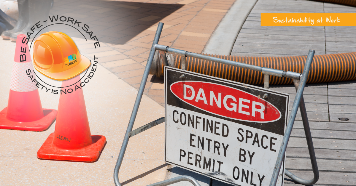
Static electricity is a major cause of fires and explosions when working with Permit Required Confined Space, (PRCS).
Is your team taking the steps to minimize the hazard of electrostatic spark ignition of flammable or combustible vapors and dusts?
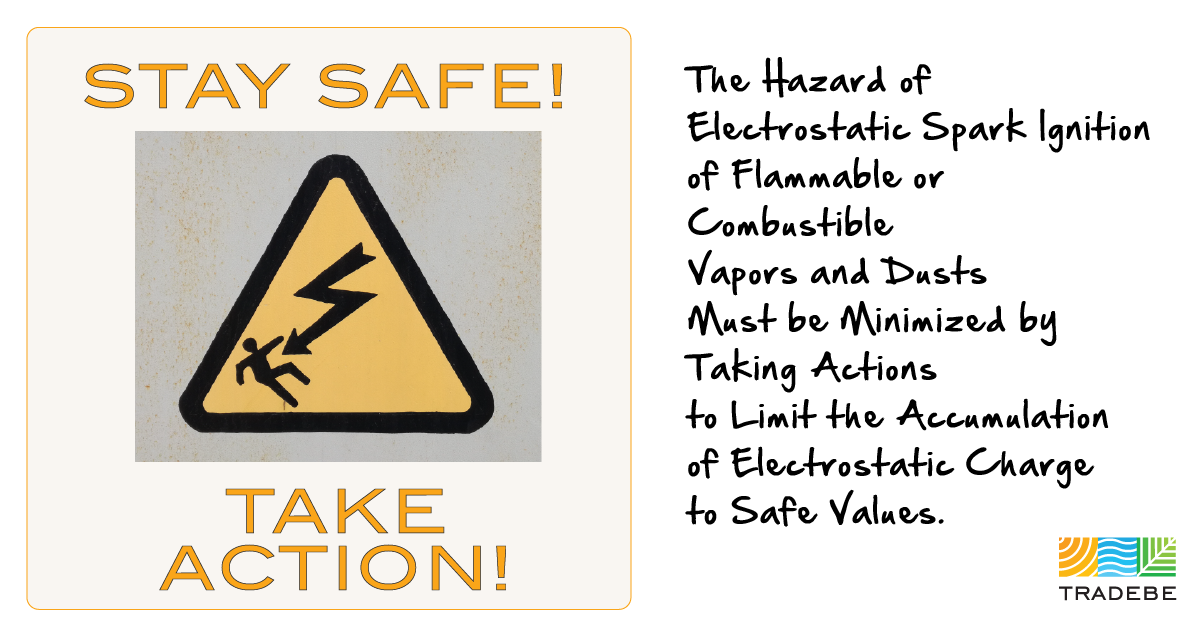
The hazard of electrostatic spark ignition of flammable or combustible vapors and dusts must be minimized by taking actions to limit the accumulation of electrostatic charge to safe values.
Static electricity is most commonly generated by liquids or solids flowing through pipes, and in mixing, pouring, pumping, filtering, or agitating.
STATIC ELECTRICITY - RATE OF GENERATION INFLUENCERS
The Static Electricity Rate of Generation is Influenced by:
- conductive properties of the liquid or solid,
- amount of turbulence in the material,
- interfacial surface between the material and other surfaces,
- velocity, and
- presence of impurities.
STATIC ELECTRICITY - COMMON LOCATIONS
Some specific locations where static electricity is generated include, but are not limited to the following:
- Piping systems: In piping systems, the generation rate and the subsequent accumulation of static charge are a function of the flow rate, material velocity, pipe diameter, and pipe length;
- Filling or transfer operations: Turbulence experienced in filling or transfer operations, caused by large flow rates, splashing or free-falling materials, greatly increases the charge accumulation above the level generated in piping systems;
- Filtration: Filters, because of their large surface area, can generated as much as 200 times the electrostatic charge generated in the same piping system without filtration; and
- Dispersing operations: Dispersing operations can be particularly hazardous in view of the extremely high rate of charge generation when liquid or solid particulates are present. With poorly conductive materials, the charge accumulation can cause hazardous sparking in the vapor/air space, such as to an exposed agitator blade in a mixer or to a conductive fill pipe. High charge generation rates can also occur when materials are mixed, thinned, tinted, or agitated.
In addition to being dependent on the charge generation rate, charge accumulation is a function of the resistance of the patch by which charges dissipate. The dissipation of static electricity is dependent on a property shown as conductivity. Materials with low conductivities tend to accumulate static charges.
STATIC ELECTRICITY - PROCEDURES TO REDUCE HAZARDS
Although the generation of static electricity cannot be eliminated, its rate of generation and accumulation can be reduced by the following procedures:
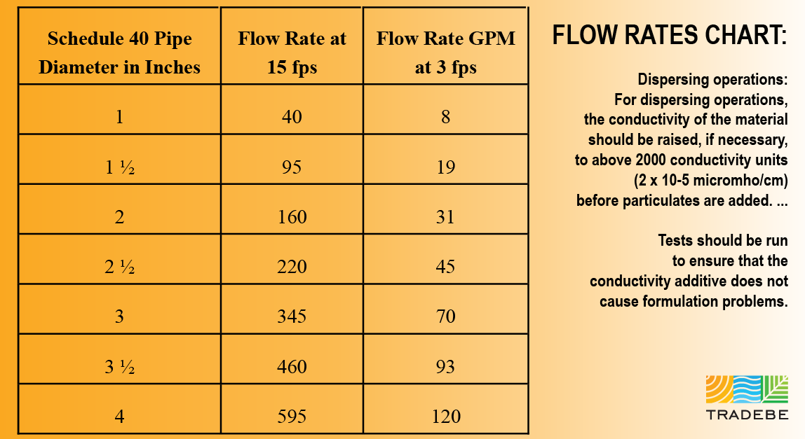
- Piping systems: The most effective method of reducing the accumulation of static charges in piping systems is through proper sizing to keep liquid velocities low. A recommended maximum velocity is 15 feet per second (fps). The following table lists the flow rates for various pipe sizes for a velocity of 15 fps.
- Filling or transfer operation: Splash filling and free-fall of flammable or combustible materials should be eliminated to the maximum extent practical by lowering flow velocities, by providing diverters to direct discharge down the side of the grounded vessel being filled, or by submerging fill pipes below product levels in the vessel. In bulk operations the velocity of the incoming material should not exceed 3 fps until the pipe outlet is covered; the velocity may be then increased to the 15 fps. The following table also list the flow rates for various pipe size for the velocity of 3 fps.
- Filtration: Experience has shown that this hazard may be controlled by installing filters far enough upstream of discharge points to provide a 30-second material relation time prior to discharge. The required relaxation time depends on the conductivity of the material, the velocity of the material, and the type of filter. For example, the 30 second relaxation time may not be necessary with a highly conductive liquid.
- Dispersing operations: For dispersing operations, the conductivity of the material should be raised, if necessary, to above 2000 conductivity units (2 x 10⁻⁵ micromho/cm) before particulates are added. If possible, polar materials should be added before non-polar materials. In some instances, proprietary anti-static agents, developed for use with fuels, can be used as additives to reduce the charge accumulation. Typically, only a few parts per million of the additives are required. Tests should be run to ensure that the conductivity additive does not cause formulation problems.
BONDING AND GROUNDING are very effective techniques for minimizing the likelihood of an ignition from static electricity.
A Bonding system connects various pieces of conductive equipment together to keep them at the same potential. Static sparking cannot take place between objects that are the same potential.
Grounding is a special form of bonding in which conductive equipment is connected to an earthing electrode or to a building grounding system to prevent sparking between conductive equipment and grounded structures.
In potentially flammable or explosive locations, all conductive objects that are electrically isolated form ground by nonconductors such as nonconductive piping or hoses, flexible hoses, flexible connections, equipment supports, or gaskets, should be bonded.
An isolated, conductive object can become charged sufficiently to cause static spark. 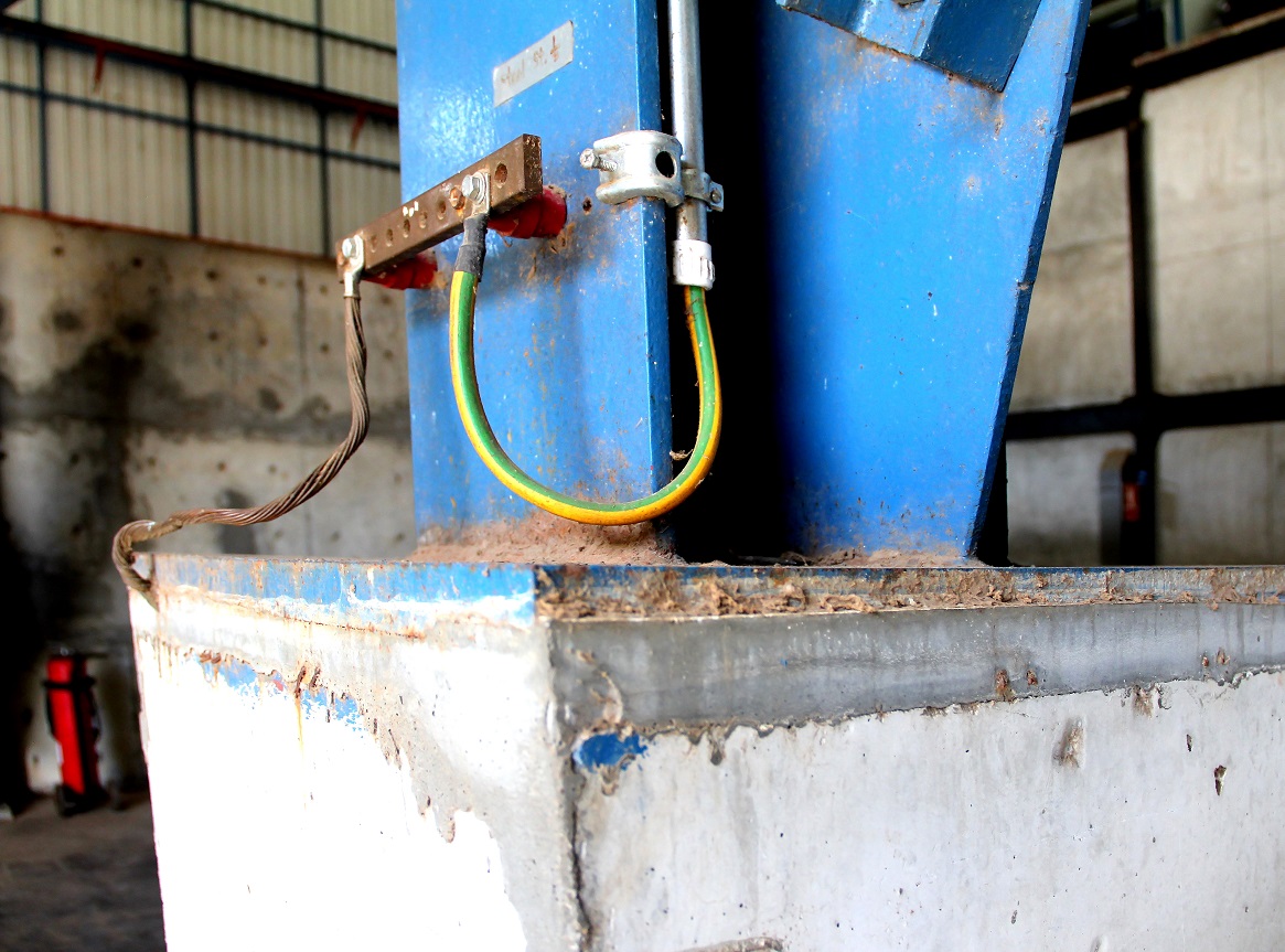
Bonding and grounding cables must be durable and of low resistance. Connections of bonding conductors to process equipment must be direct and positive for portable equipment, uninsulated copper or stainless steel, aviation-type flexible cable and single-point clamps should be used. These clamps will contact metal surfaces through most paint, rust and surface contaminants. The single-point clamps are superior to the battery-type and “alligator” type clamps for making direct contact.
Large diameter grounding cables are commonly used to minimize mechanical damage rather than for current-carrying capacity. These cables carry microampere-level electrical currents. An arbitrary value of maximum resistance (e.g., 25 ohms) from each bonded object to the grounding bus is specific to that periodic checks of the bonding and grounding system with a simple ohmmeter can confirm that the system is intact and in direct contact with the bonded objects.
Caution must be exercised in the installation of static grounding systems not to use as a ground, any part of the electrical current-carrying system. Fires caused by electrical arcing from current feedback through the grounding system may occur where static-control grounds are tied into the electrical system neutrals.
The proper installation of bonding and grounding devices is critical in protection of personnel and equipment.
At the time of installation, a resistance test must be completed to confirm electrical continuity to ground. In addition, an effective inspection and maintenance program is required for each system to ensure continued continuity of the system.
In evaluating inspection and maintenance requirements, the bonding and grounding system can be divided into three categories as follows:
- The point-type clamps equipped with flexible leads used for temporary bonding of portable equipment, container, etc. to existing grounding systems;
- The fixed grounding cables and bus bars used to connet the flexible leads and fixed equipment to ground; and
- The earthing electrode itself.
The flexible leads are subject to mechanical damage and wear, as well as corrosion and general deterioration. For this reason, they must be inspected as least weekly. This inspection should evaluate cleanliness and sharpness of the clamp points, stiffness of the clamp springs, evidence of broken strands in the cables, and solidity of cable attachments. A test should be made using an intrinsically safe ohmmeter to test ohmic resistance and continuity. To complete this test, one lead of the ohmmeter is connected to a clean spot on the item, the other lead is connected to the grounding bus, metallic piping, or other fixed equipment. The measured resistance should be less than 25 ohms and will usually be about 1 ohm.
For more information: Grounding and Bonding Applications published by Stewart R Browne.
This is the most complete reference document on this topic in my opinion and should be referenced in anything pertaining to static electricity.
The fixed leads and the bus bars are not usually subject to damage or wear as the temporary connectors. These are required to be checked with an ohmmeter on a per project basis, and at least annually. One lead of the ohmmeter must be connected to the fixed lead or bus bar; the other lead should be connected to the earthing electrode or to existing ground. The measure resistance should be less than 1 ohm.
Conductive hoses are required to be checked weekly, and after repair or replacement for electrical continuity and resistance. The conductive segments may break and may not be repair properly, thus rendering the hoses nonconductive or with an abnormally high resistance. Nonconductive hoses having an internal, spiral conductor are required be installed so that the spiral conductor contacts adjacent metallic fittings.
The final component of the bonding and grounding system is the earthing electrode that passes static charge into the soil or to earth. This may be a device installed solely for grounding purposes, such as a driven rod or buried plate, or it may be an existing underground metal system. If a building or process is grounded for lightning protection or otherwise effectively grounded, this grounding is adequate for static grounding. A separate static earthing electrode is not needed.
Underground piping equipped with cathodic protection is not a suitable ground. Underground piping made of cement-asbestos or plastic would not be satisfactory as a ground. It is also possible for metal piping to have sections of plastic or cement-asbestos which would make it unsatisfactory.
Water meters should have jumper cables permanently installed around them to provide a continuous electrical path. When underground piping is utilized as a ground, any disconnections for alterations or repair may make the ground system ineffective.
Sprinkler piping and electrical conduit should be avoided because of the increased resistance to ground caused by joints and connectors. A break in continuity can also result when piping and conduit are removed for repair or alterations.
“Be Safe - Work Safe. Safety is No Accident!”
Jeremy Paradis, Director of Health & Safety, Tradebe USA
#HealthandSafety #StaticElectricity #GroundingandBonding #BeSafeWorkSafe #SafetyisNoAccident
At Tradebe, our priorities are safety and the protection of people and the environment. Safety is a common “water cooler” topic here at Tradebe where a culture of Safety is Top Priority. If Safety is important to your business, catch the latest buzz: Subscribe Now…
Resources:
Subscribe to Tradebe Safety Blog, news and more...
https://www.osha.gov/Publications/3075.html
https://www.osha.gov/SLTC/hazardouswaste/finalsitesafetystudy.html
http://www.srbrowne.com/booklet/index.html